|
|
|
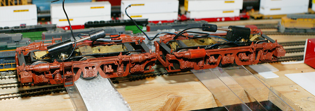
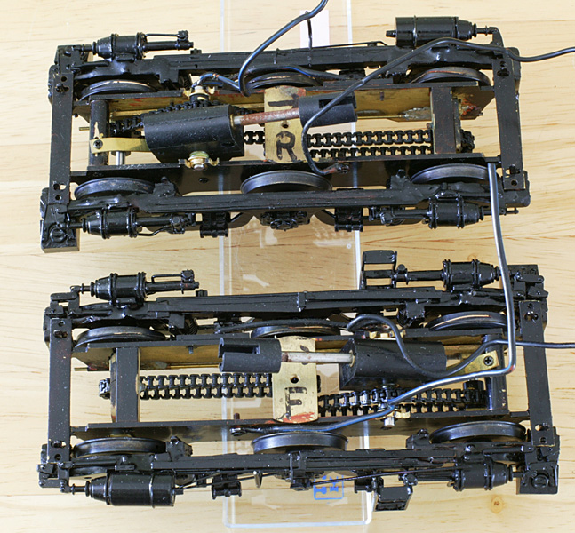
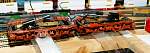
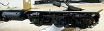
Bogies
in primer - June 2006. The first time I saw a 9mm loco with
chain drive I thought that was a little odd. but it works!
|
 |
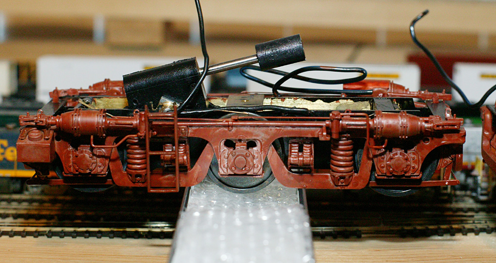
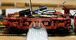
| Some
August pictures: The fuel tank assembly and brass base plate
were modified to raise the fuel tank and air reservoirs up a
little closer to the body |
|
 |
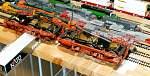
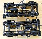
| The
bogies have now had most of the extra details added. In this
view the speedo, HSL recab brake cylinder and its associated
piping can be seen. One more pipe to be added... in their later
lives, most of the DGs had sandboxes on the outboard ends of the
bogies only. |
|
 |
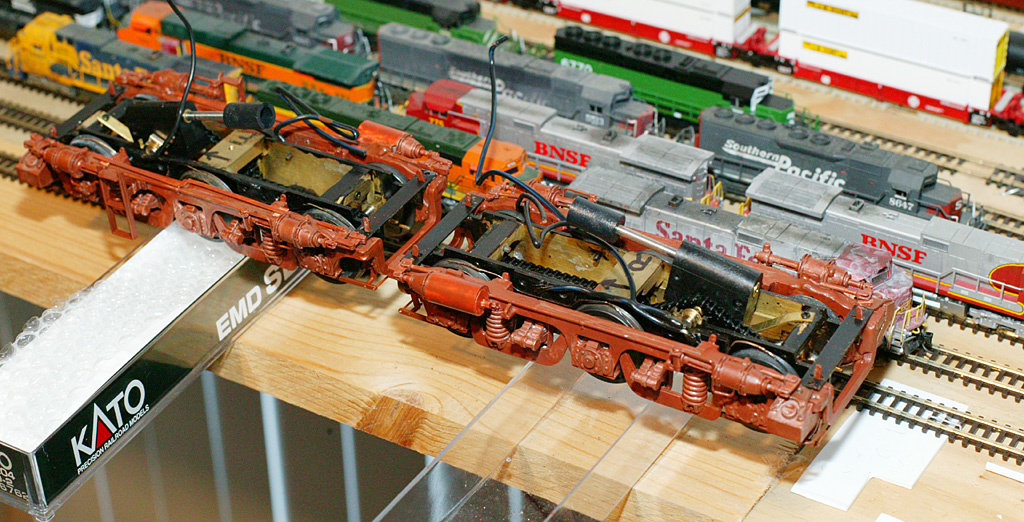
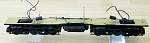
| View
from on high. I cheated a little by cutting back the brake
actuating levers so they clear the stretchers across the ends of
the bogie "inners" (rather than sitting on top them
after everything is screwed together for the last time) so I can
take the outers off at leisure. I doubt this will be too visible
when the body goes on. I'm also trying to avoid cutting the
middle out of those stretchers as I have little faith in my
soldering skills.... The inners (brass) were soldered. Being a
man of little talent in the soldering department, the outers (whitemetal)
are completely superglued with araldite slopped on for
reinforcement. Same for the fuel tank assembly. Classy. |
|
 |
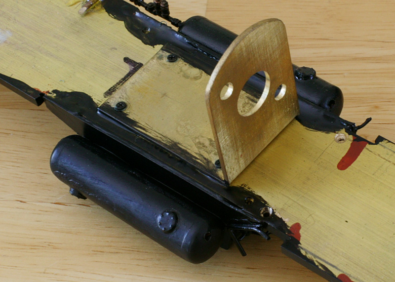
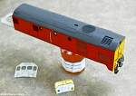
| View
of the chassis pieces sitting together |
|
 |
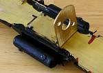
| An
experiment with fabricated grilles made up of a stack of angle
brass of alternating sizes. I think this looks pretty good, but
is hard work...! I've done the dynamic brake grille (shown) and
the radiator grilles this way and will probably use plasticard
for the blower inlet and the smaller square side grilles. On the
real thing, the ones I'm doing in plasticard seem to have a
finer pitch than the others, so although it might look like a
mistake... it seems to be the way the real things are. |
|
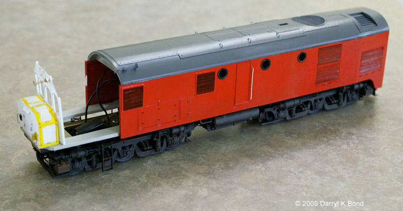
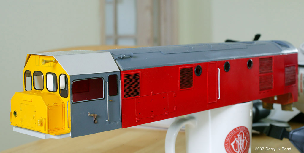
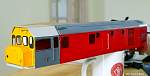
August
2008. Finally some progress after a 2 year hiatus.
|
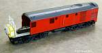 |
| Overall
views. Still haven't put the rear ladder on yet
|
|
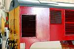 |
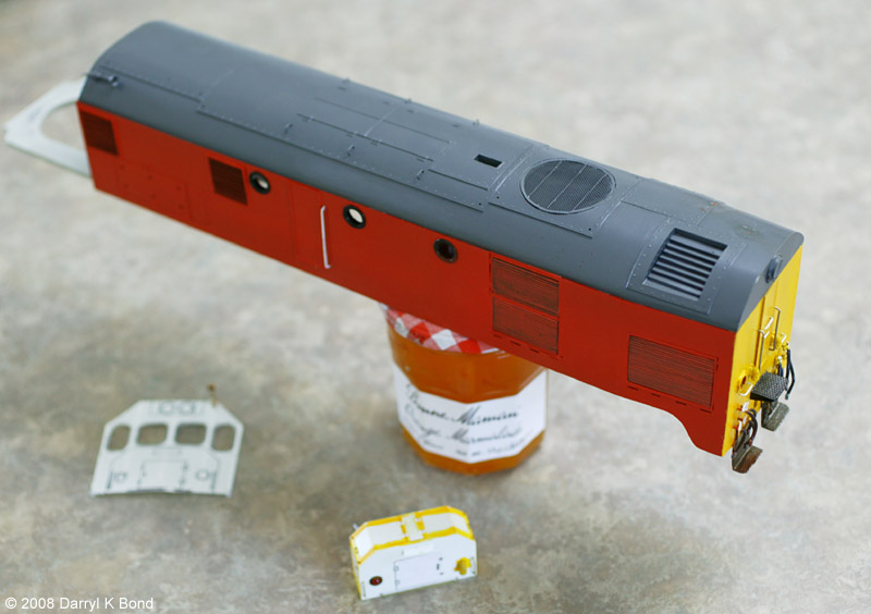
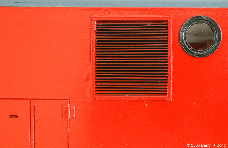
| Never,
ever take close up pics of your models... These are the three
styles of grilles in use on the model. The brass ones on the
rads (right) and the dynamic housing on the port side rear;
plasticard ones on the blower inlet (left) and the small square
intake grilles on the port side; the kit ones, used for the 4
square inlets on this side mainly out of laziness and as an
excuse, I was running out of plasticard strips... |
|
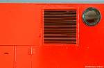 |
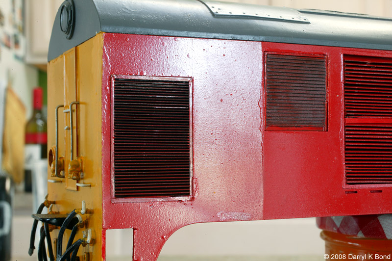
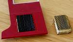
| One
of the plasticard square grilles three or four times life size.
These look quite tasty. This has been my first attempt at
airbrushing as well which came out OK to the observing eye but
not so well under extreme magnification, so these pics are
a bit of a shock! Model Master Italian Red, or should that be Rosso,
Insignia Yellow and Gunboat Grey for those taking notes. The red
could be a smidge more yellowy/orangy but its as close as I've
come in a commercial paint |
|
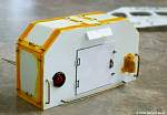 |
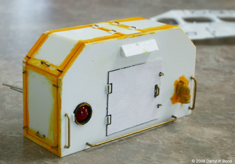
| Recab
nose. In a masochistic kind of way I rather enjoyed making those
little door latches. And before you all go making nasty
comments, this is three times real size on a 'normal'
sized monitor. The cab front in need of straightening and sides
are very thin plasticard in the hope of getting near flush
glazing were made using the toner transfer method - laser
printing the plan onto glossyish photo paper and ironing onto
brass, or in this case plasticard while trying not to melt it... |
|
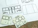 |
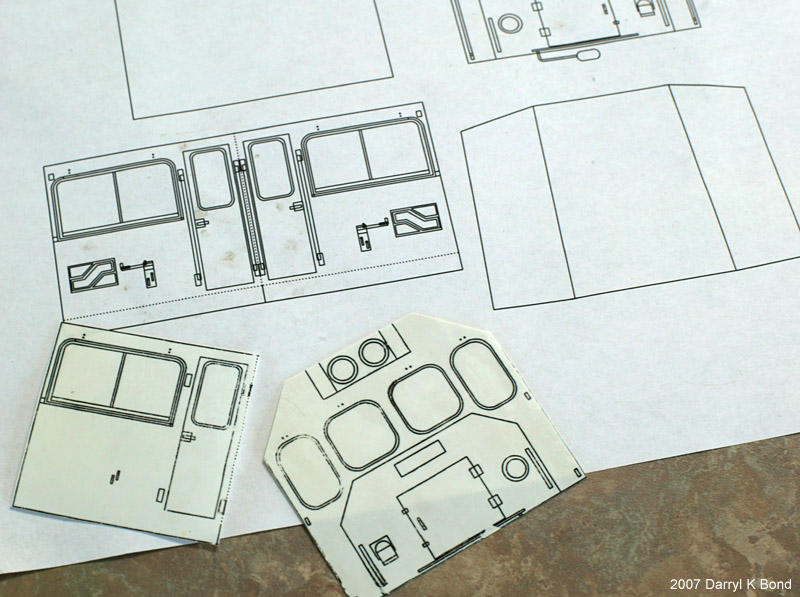
| Recipe
for cab parts in superthin styrene: 1) Autocad up a plan 2)
laser print on glossyish not to fancy photo paper 3) Iron the
back of the paper to transfer the toner to the styrene. 4) Cut
out, layer and embellish with detail. Requires some patience and
practice. Here's one I prepared earlier. |
|
 |
| Test
fitting the cab with a temp cab roof |
|
|
|